Repurposing an HP 83300A Remote Interface
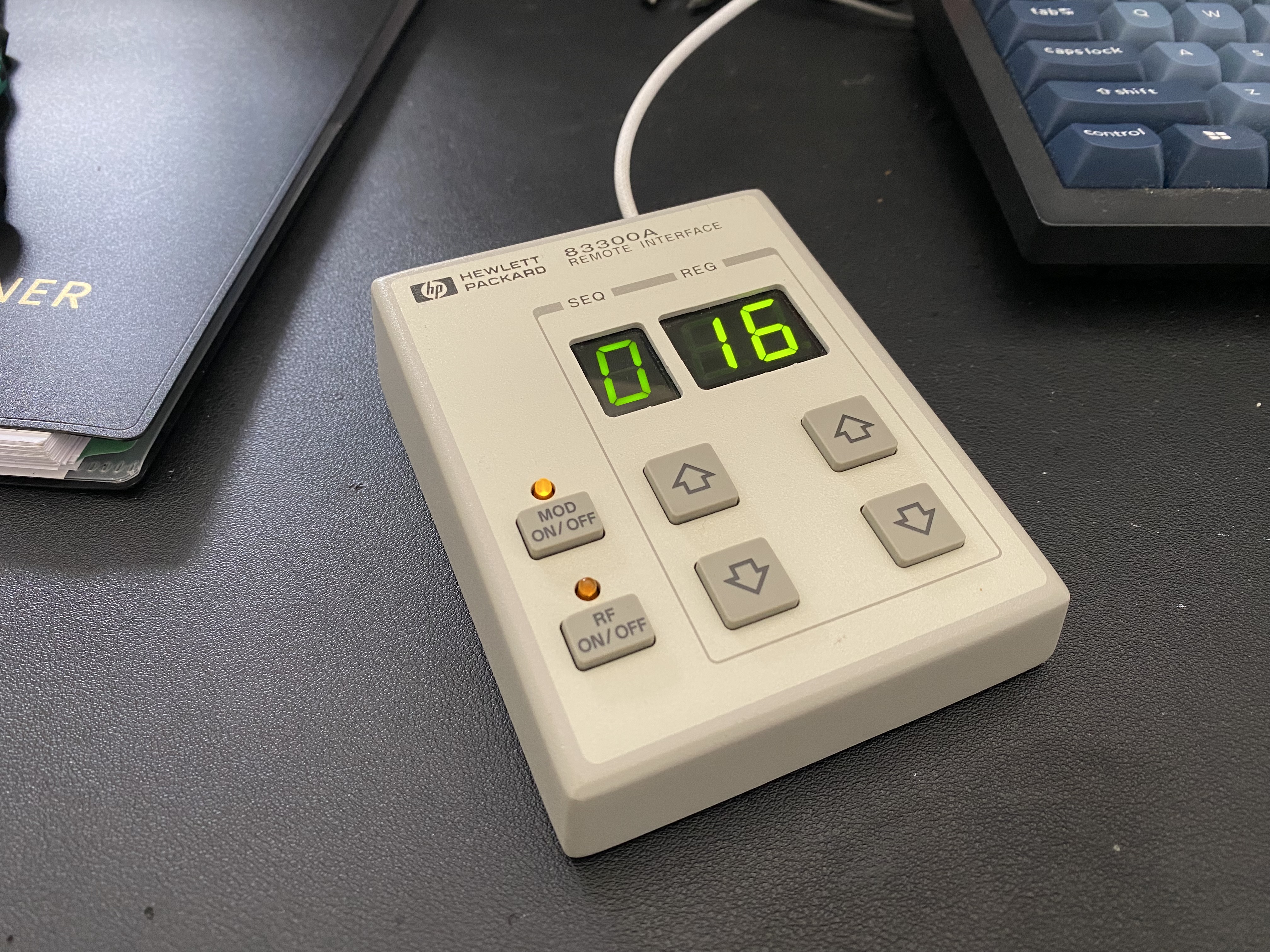
Many years ago, I saved this little HP remote interface box out of the trash. It was originally intended to be used with a radio frequency signal generator. It has two numeric 7-segment displays (one with a single digit and one with two), up/down arrows for each, and two function toggle buttons with status LEDs. It seemed too nice to throw away, and the displays/controls are generic enough to be repurposed. I enjoy physical controls, and have somewhat of a habit of repurposing old control panels, either to adapt them to modern equipment or completely new uses. Switches, buttons, knobs and lights never really go obsolete, after all.
So, I grabbed it and tossed it in my hoard of potentially useful electronic junk to maybe use for something someday. I’ve taken it apart to look at the circuitry a handful of times since then, but never got around to doing anything with it. But with a project in mind where it might be useful, I found myself taking another look.
Inside, I rediscovered the reason I’ve likely set it aside every time I’ve looked at it. The buttons are simple enough, with no multiplexing or matrixing. The three 7-segment displays and two status lights are driven by a set of three 8-bit D flip-flops (74HC574As). They share an 8-bit data bus, wired to a 68HC05 microcontroller. The clock lines are wired to individual microcontroller pins so that it can latch new values into each. 8 data lines and 3 control signals isn’t a huge amount of lines to wire up, but 6 switches plus 11 lines for the LEDs would need 17 GPIOs total, more than the small microcontroller dev boards that I had around. On top of that, most modern MCUs have 3.3V GPIOs, and the input on the 74HC574As would be iffy when running at 5V.
I briefly poked at trying to reverse engineer the original interface. The only connector on the device was a male DE-9, which appeared to match the standard RS-232 pinout, and connected to the 68HC05 with a MC145407 RS-232 transceiver chip. The board pulls power from the DTR signal. Connecting it to a serial port and setting DTR high powered it up—it shows “HP” on the 2-digit display. But pushing the buttons didn’t generate any activity on the port, and sending it random bytes didn’t affect the LEDs. Without any clues to the protocol, and without the signal generator that it would have been paired with to be able to monitor communications, re-using the original interface seemed like a dead end. (There’s also no documentation available—I can barely find references that suggest that this thing even existed).
I desoldered the 68HC05 microcontroller, RS-232 transceiver, and the three 8-bit flip-flops. In their place, I soldered on a set of three 74HCT595 shift registers, which are very common for driving LEDs in more modern hardware. The 74HCT series has input thresholds that are compatible with 3.3V outputs when powered from 5V, so I can run them from 5V and don’t have to change all of the LED resistors to get the same brightness. The shift registers, chained together, can be driven from just three pins on the microcontroller, and using an SPI peripheral to do this makes the software very simple. The capacitors for the transceiver and the crystal for the 78HC05 were left in place—with the chips removed they’re not connected to anything.
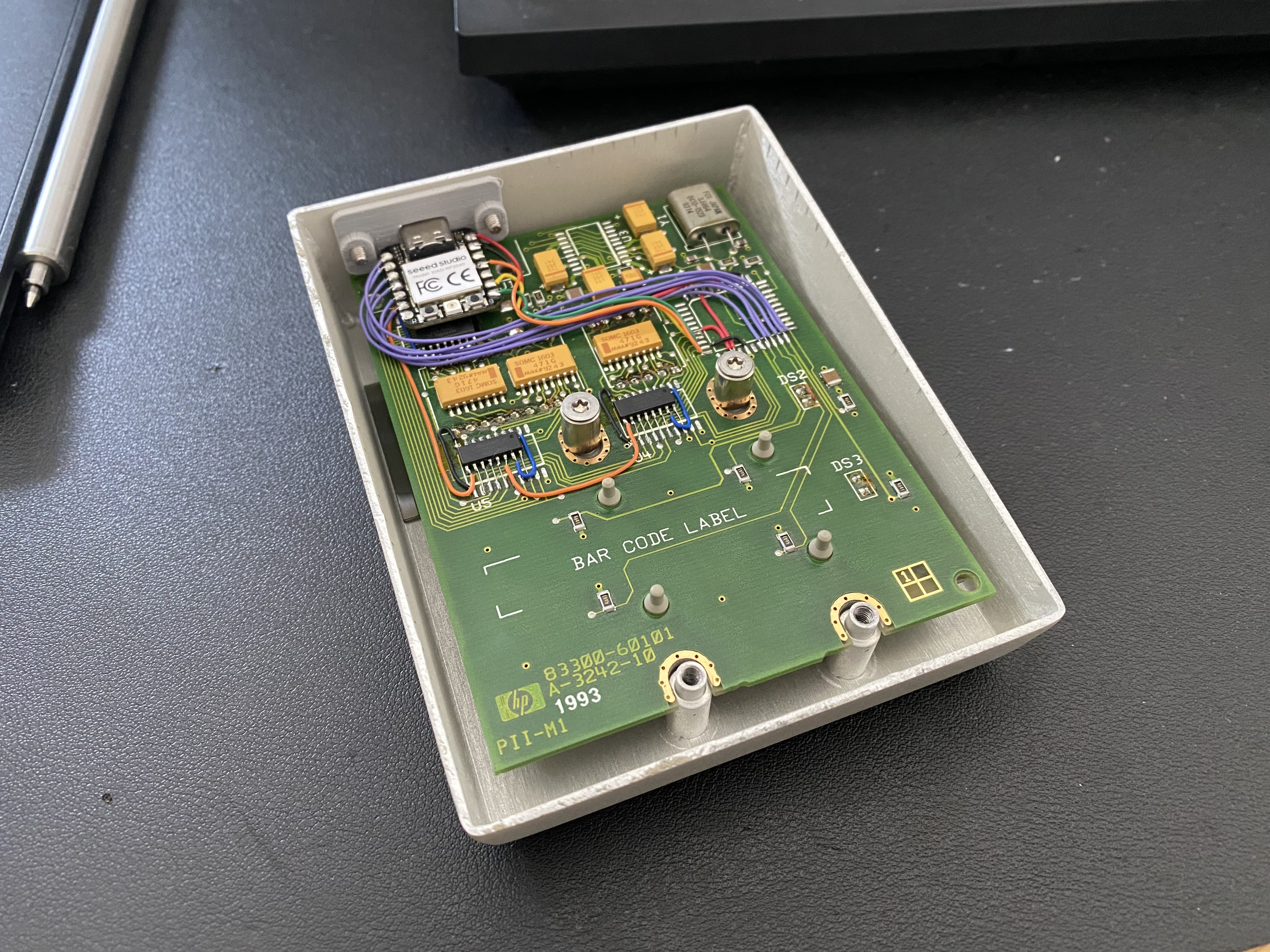
I had to get a little creative wiring the shift registers. The flip-flops had all of their outputs along one side of the chip. A 595 shift register has seven of its outputs on one side, but the last bit is on the other. I soldered on the 7 pins that do line up, masking off the 8th pin (which is ground on the 595 but is VCC on the 574A) with kapton tape. The ground (black wire) and QA (blue wire) lines get wrapped around to the other side of the chip with bodge wires. The data line (orange wires) gets chained from one shift register to the next, creating a 3-byte chain. For the remaining signals, including VCC, I took advantage of the traces that originally carried the 8-bit data bus. These signals (clock, latch, output enable, VCC, and reset) tie all three chips together in parallel. I bridged them across (the 595 chips are narrower than the 574As) with short wire jumpers.
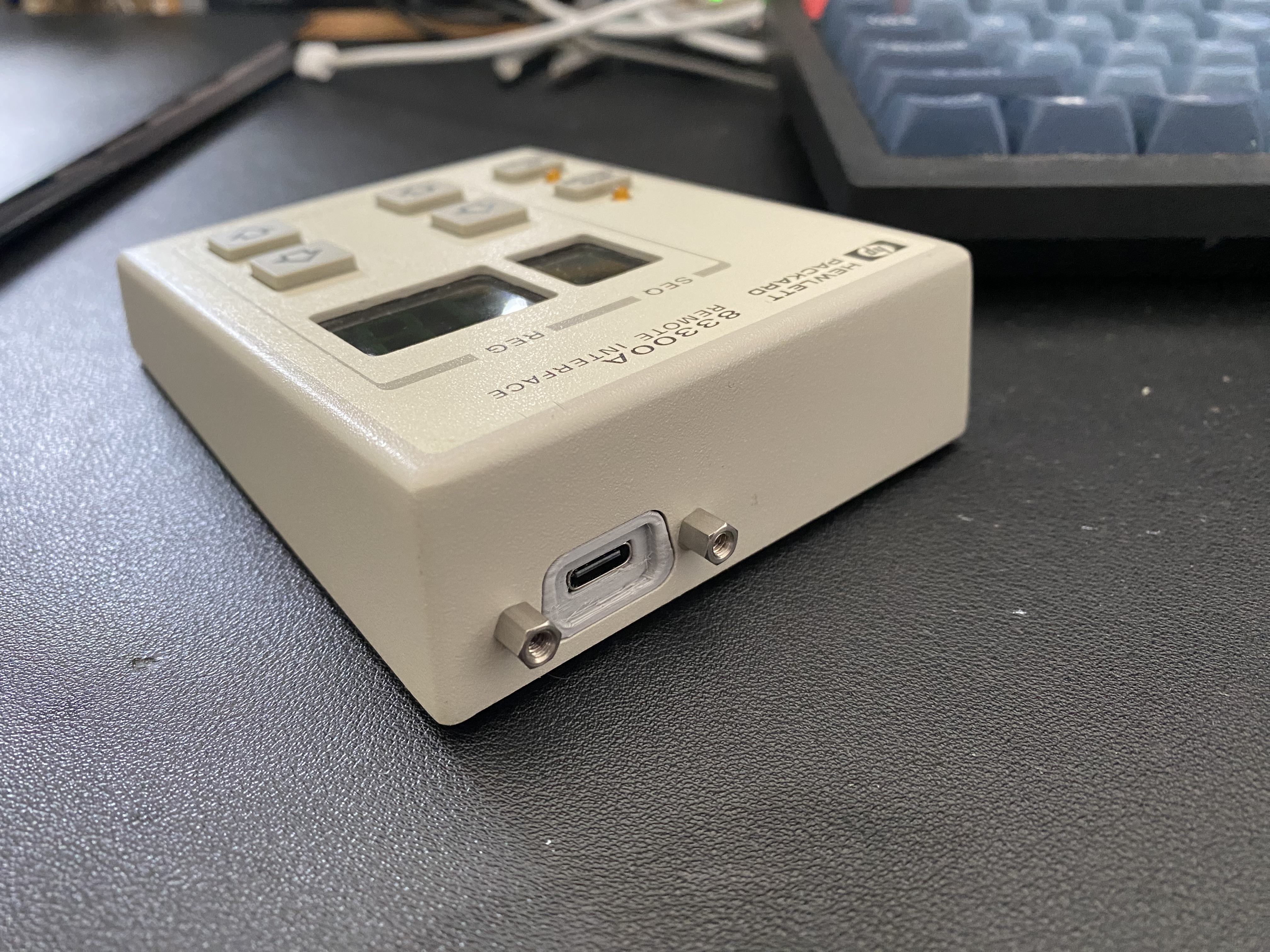
For the new interface, I used a Seeed RP2040 Xiao board, which fit the requirements of being compact and having a USB-C interface, plus the all-important requirement of already being on hand in my parts bin. I 3D printed a small part to hold the Xiao, which fits into the opening left by the original DE-9 connector, held in place by the original screws. The connections to the Xiao are all made via the pads from the removed 68HC05, which keeps the wiring relatively neat and tidy. The six lines for the buttons (purple) wire to the GPIOs along the left edge of the Xiao, and the shift register signals (data, latch, and clock) wire to the SPI0 peripheral on the right side, along with 5V and GND. The output enable and reset signals for the shift registers are permanently tied to GND and VCC.
The firmware is pretty simple. It enumerates as a USB HID device, with
vendor-defined usage. I implemented three report types. The INPUT report is
just a single-byte bitmap that contains the status of the six buttons. There
are two OUTPUT reports: one that takes numeric values for the two displays,
and one that takes a raw segment bitmap to allow any arbitrary pattern of
segments to be displayed. Both reports have bitfields for the two discrete
status LEDs.
And with that, it’s fully modernized and buttoned back up. Now we’ll see if I ever get around to the project that I intend to use it with, so that it can actually control something.
As a concluding remark, it’s an incredibly well-built device. The original was clearly intended to be used inside an RF anechoic chamber, where RF leakage needs to be kept to an absolute minimum. The case is made from thick steel, and all of the seams are welded and ground smooth. The bottom plate has copper fingers that go all the way around, leaving no gaps for stray RF energy to escape. This probably also figured into the decision to have dedicated flip-flops for all of the LED segments and dedicated inputs for all of the buttons rather than scanning them, keeping the number of changing signals to the absolute minimum.